
Flash an ESP32 breakout board through the Raspberry Pi 3's UART
ESP32 chips are available as development boards with a USB interface and integrated USB/serial converter, or as “buttoned breakout boards” without any additional circuitry.
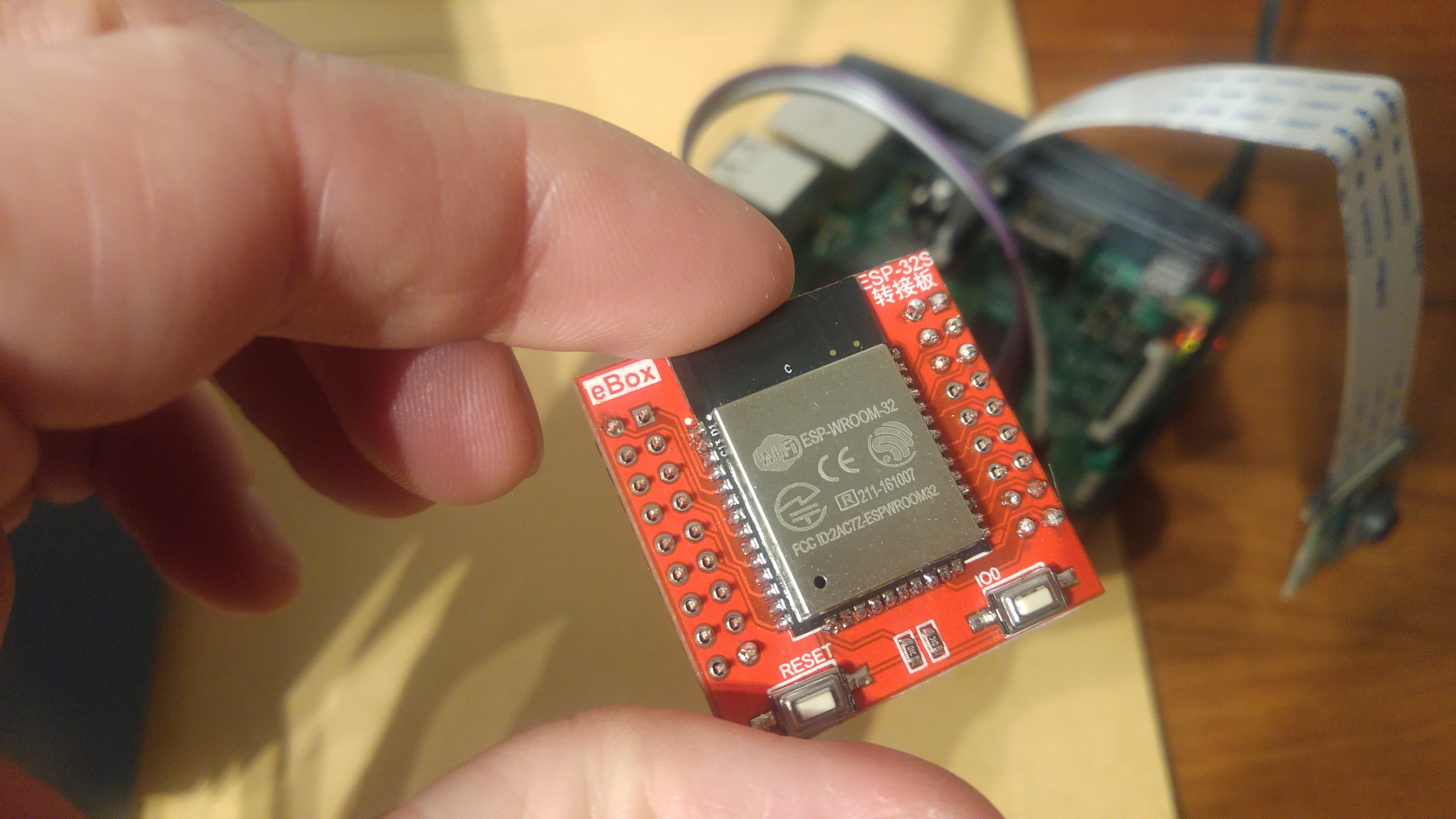
But what do you do without a separate 3.3-volt RS232 converter? You use your Raspberry Pi.
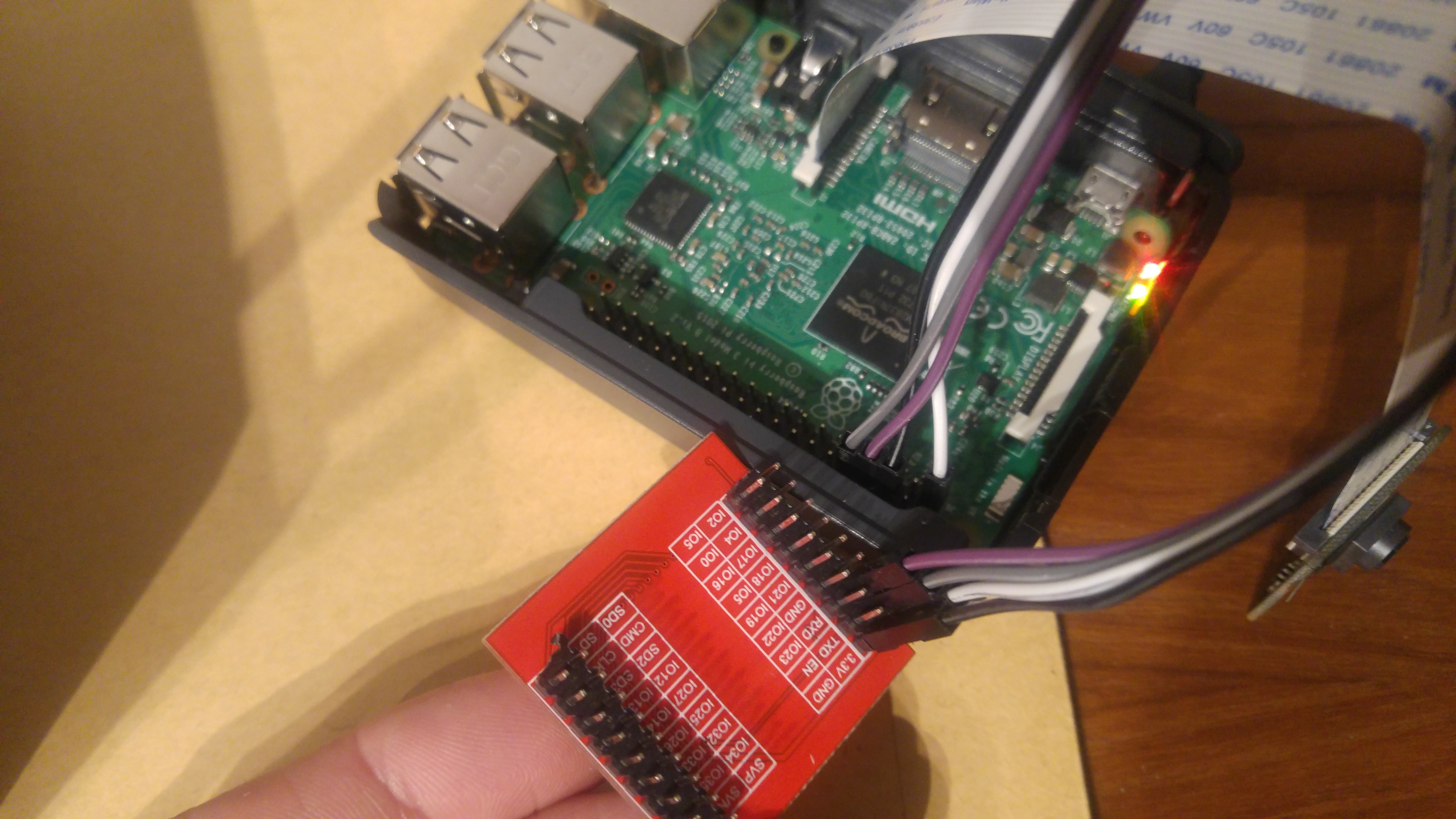
The wiring is as follows:
| Raspberry Pi | ESP-32 |
|---|---|
| Tx | Rx |
| Rx | Tx |
| Ground | Gnd |
| 3.3V | 3.3V |
I compile my program on my main PC and use the Raspberry only for programming, because installing the ESP32 toolchain on the Raspberry Pi is rather complicated.
So first create and compile an ESP32 program on the PC. Instead of Arduino, I use platformio, because.
cd ~
mkdir esp32
cd esp32
virtualenv --python=python2.7 venv_platformio
. ./esp32/venv_platformio/bin/activate
pip install platformio
mkdir wifitest
cd wifitest
platformio init
Now add the following to ~/esp32/wifitest/platformio.ini:
[platformio]
env_default = esp32


[env:esp32]
platform = espressif32
framework = espidf
monitor_baud = 115200
board = lolin32
board_flash_mode = dio
The selected board does not matter.
Create a file ~/esp32/wifitest/src/main.c based on the official template:
#include "freertos/FreeRTOS.h"
#include "esp_wifi.h"
#include "esp_system.h"
#include "esp_event.h"
#include "esp_event_loop.h"
#include "nvs_flash.h"
#include "driver/gpio.h"

esp_err_t event_handler(void *ctx, system_event_t *event)
{
    return ESP_OK;
}

void app_main(void)
{
    nvs_flash_init();
    tcpip_adapter_init();
    ESP_ERROR_CHECK( esp_event_loop_init(event_handler, NULL) );
    wifi_init_config_t cfg = WIFI_INIT_CONFIG_DEFAULT();
    ESP_ERROR_CHECK( esp_wifi_init(&cfg) );
    ESP_ERROR_CHECK( esp_wifi_set_storage(WIFI_STORAGE_RAM) );
    ESP_ERROR_CHECK( esp_wifi_set_mode(WIFI_MODE_STA) );
    wifi_config_t sta_config = {
        .sta = {
            .ssid = "SSID",
            .password = "passwrd",
            .bssid_set = false
        }
    };
    ESP_ERROR_CHECK( esp_wifi_set_config(WIFI_IF_STA, &sta_config) );
    ESP_ERROR_CHECK( esp_wifi_start() );
    ESP_ERROR_CHECK( esp_wifi_connect() );

    gpio_set_direction(GPIO_NUM_4, GPIO_MODE_OUTPUT);
    int level = 0;
    while (true) {
        gpio_set_level(GPIO_NUM_4, level);
        level = !level;
        vTaskDelay(300 / portTICK_PERIOD_MS);
    }
}
Compile it with
platformio runFor all platformio commands, make sure that the virtual environment into which platformio was installed is active. Activate it with . ./esp32/venv_platformio/bin/activate and deactivate it with deactivate.
The esp-idf toolkit must be installed on the Raspberry Pi, because it contains the tool used for flashing.
# Raspberry
sudo apt-get install git python python-serial
cd ~
mkdir esp32
cd esp32
git clone --recursive https://github.com/espressif/esp-idf.git
The serial port must also be released; it is currently still being used as a login shell.
sudo raspi-config
# -> Interfacing-Options
#   -> Serial
#     -> Would you like a login shell to be accessible over serial? -> No
#     -> Would you like the serial port hardware to be enabled? -> Yes
# -> Finish
#   -> Reboot now
Since Raspberry Pi version 3, the serial interface is no longer /dev/ttyAMA0, but /dev/ttyS0. AMA0 is instead the serial interface used by the Bluetooth functionality.
Now create a script on the Raspberry Pi that fetches the files from the main PC and flashes them to the ESP32: ~/esp32/get_and_flash.
#!/bin/bash

REMOTEBUILDDIR=daniel@yak.local:esp32/wifitest/.pioenvs/esp32/

mkdir -p tmp
scp ${REMOTEBUILDDIR}partitions_table.bin tmp
scp ${REMOTEBUILDDIR}firmware.bin tmp
scp ${REMOTEBUILDDIR}bootloader.bin tmp

. ~/esp32/venv_platformio/bin/activate

python2.7 ~/esp32/esp-idf/components/esptool_py/esptool/esptool.py --chip esp32 --port "/dev/ttyS0" --baud 115200 --before default_reset --after hard_reset write_flash -z --flash_mode dio --flash_freq 40m --flash_size detect 0x1000 tmp/bootloader.bin 0x8000 tmp/partitions_table.bin 0x10000 tmp/firmware.bin
I extracted the addresses and the complete command from platformio run --target upload -v.
Now all that is missing is some way to flash over the air.